Circularly Polarized Coverage From a 0.73kg Outdoor Panel
5dBi of gain, an 80° by 70° beam at 3dB, and 0.73kg on the pole once the bracket is fitted.
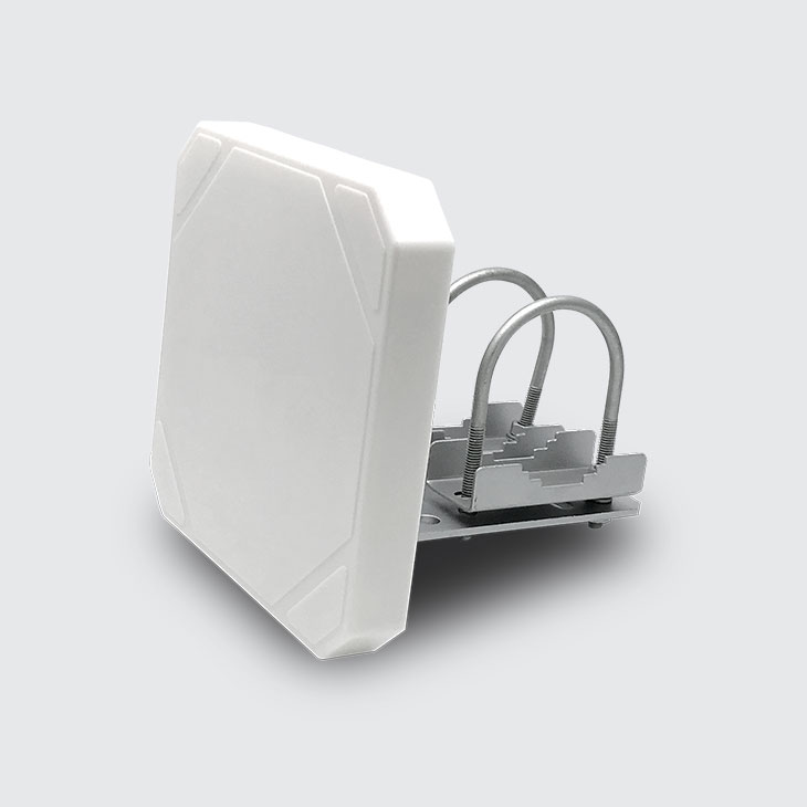
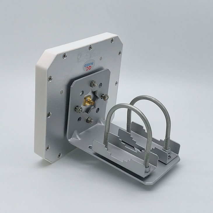
The panel puts 5dBi of right-hand circularly polarized gain into an 80° by 70° pattern at 3dB, so tag orientation costs you far less than it does under a linear panel. A front-to-back ratio of ≥17dB holds energy off whatever stands behind the aperture, and VSWR stays at ≤1.3 across 902-928MHz and 865-868MHz. Molded ABS covers an aluminum radiant board, sealed to IP67 and rated for 60m/s wind between -40°C and +60°C. The single SMA female port sits at the center of the back plate, inside the footprint of a bracket that clamps a φ30-φ50(mm) pole or screws flat to a wall.
- 902-928MHzFrequency range, band one
- 865-868MHzFrequency range, band two
- 5dBiGain
- RHCPRight-hand circular
- 50ΩInput impedance
- 20WMax input power
- SMA femaleConnector type
- DC GroundedLightning protection
- 60m/sRated wind velocity
- AluminumRadiant board material
- 0.73kgWith mounting bracket
- φ30-φ50(mm)Support pole diameter
Overview
The 5dBi Panel Antenna is a passive UHF panel for fixed readers that have to work outdoors. A single antenna is specified for both 902-928MHz and 865-868MHz, so a rollout that crosses bands does not split into two stock codes. Gain is 5dBi, polarization is RHCP, and the 3dB pattern measures 80° in the H-plane by 70° in the E-plane.
What separates this panel is what it turns away. A front-to-back ratio of ≥17dB and a VSWR of ≤1.3 keep the energy inside the lobe the installer aimed, which is what decides whether two portals facing each other across an aisle stay out of each other's tags. Max input power is 20W into a 50Ω port, so a full-power fixed reader drives it directly.
Construction is molded ABS in white over an aluminum radiant board, sealed to IP67, rated for 60m/s wind and an operating range of -40°C to +60°C. Lightning protection is DC Grounded. The bracket clamps a φ30-φ50(mm) pole with U-bolts or screws flat to a wall, and the finished assembly weighs 0.73kg. Explore the full range of UHF RFID antennas.
Key Features
Radio Performance
- Frequency: 902-928MHz / 865-868MHz
- Gain: 5dBi
- Polarization: RHCP
- 3dB beam-width: 80° H, 70° E
- Front-to-back ratio: ≥17dB
Outdoor Rating
- Sealing: IP67
- Operating range: -40°C to +60°C
- Lightning protection: DC Grounded
- Rated wind velocity: 60m/s
- Radome: white ABS
Interface and Mounting
- Connector: SMA female
- Input impedance: 50Ω
- Max input power: 20W
- Dimensions: 145*145*20(mm)
- Weight: 0.73kg with bracket
Features & Functions at a Glance
A Closer Look at the Hardware
Molded ABS RadomeThe white ABS radome is one molded piece with chamfered corners, and no fastener heads break the front face. The body measures 145*145*20(mm).
SMA Female Port on the Back PlateThe SMA female connector sits at the center of the back plate, inside the area the bracket covers, so the coaxial tail runs behind the panel instead of past its edge.
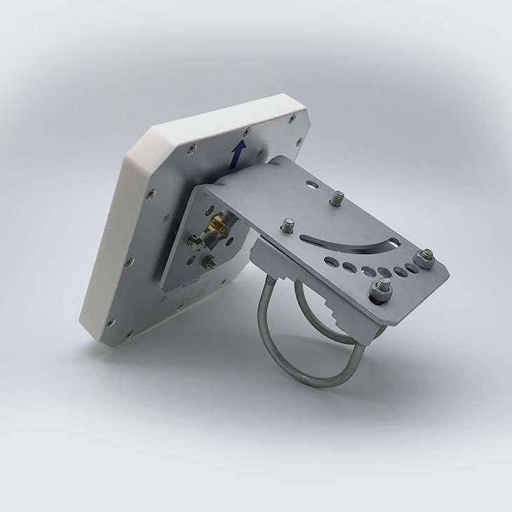
Tilt Bracket and U-BoltA curved slot in the bracket sets the down-tilt angle, and the U-bolt closes around a φ30-φ50(mm) pole. The same plate takes screws when the panel goes flat on a wall.
Specifications
Electrical
- Frequency Range
- 902-928MHz / 865-868MHz
- Polarization Type
- RHCP
- Gain
- 5dBi
- 3dB Beam-Width. H-Plane
- 80°
- 3dB Beam-Width. E-Plane
- 70°
- VSWR
- ≤1.3
- Front to back Ratio
- ≥17dB
- Input Impedance
- 50Ω
- Max Input Power
- 20W
- Lightning Protection
- DC Grounded
Mechanical
- Connector Type
- SMA female
- Dimensions H*W*D (mm)
- 145*145*20(mm)
- Weight
- 0.73kg (with mounting bracket)
- Radome Material
- ABS
- Radome color
- white
- Radiant board material
- aluminum
- Operating Temperature
- -40°C/+60°C
- Sealing
- IP67
- Installation mode
- Pole mounted or Wall mounted
- Support Pole Diameter
- φ30-φ50(mm)
- Rated Wind Velocity
- 60m/s
Every row above is transcribed from the 5dBi Panel Antenna configuration sheet. Items not listed there are not offered on this page, and IP67 sealing and the operating temperature range are design figures from that sheet, quoted without a test report number.
Why Buy the 5dBi Panel Antenna From CedaGlo
Specs You Can Measure
Every figure on this page is transcribed from the configuration sheet for this antenna, and each one is something you can put on a vector network analyzer and check yourself before the shipment leaves your dock.
Cable and Mount to Suit
Tell us the pole diameter, the cable length and the connector gender your site needs. We put the interface on the order confirmation rather than leaving your installer to find out on the day.
Test Before You Commit
Ask for an evaluation unit and hang it on the portal you actually plan to build. Range depends on your reader, your tags and the metal around them, so a bench number from anyone proves little.
Supported for the Long Run
A passive antenna carries no battery and no firmware, so nothing inside reaches an end-of-support date. Availability, warranty term and spare parts coverage are set out on the order paperwork.
Frequently Asked Questions
How much gain and how wide a beam does this panel actually give?
Gain is 5dBi. The 3dB beam-width is 80 degrees in the H-plane by 70 degrees in the E-plane, and the front-to-back ratio is 17dB or better. Read range is deliberately not quoted here, because it is set by your reader output, your tag and the metal around the portal, not by the antenna alone. Hang an evaluation unit on the portal you plan to build and measure it there.
Do I need a different antenna for 865-868MHz and for 902-928MHz?
No. The same antenna is specified for both bands, with RHCP polarization and an SMA female port in either case. VSWR is 1.3 or lower and input impedance is 50 ohms, so it presents the same load to the reader on either band. Tell us the cable length and connector you plan to run and we will put that on the order confirmation.
What is the antenna built from?
The radome is ABS molded in white, and the radiant board behind it is aluminum. The connector is SMA female and maximum input power is 20W. The mounting bracket ships with the antenna and is counted in the 0.73kg weight figure, so the mast load you plan for is the figure on this page.
How long can we keep buying and supporting this part?
A passive antenna carries no battery and no firmware, so nothing inside it reaches an end-of-support date. Warranty term, spare parts coverage and availability windows are confirmed in writing with your order, which is where you should hold us to them rather than on a product page.
How does it hold up on an outdoor pole?
Sealing is rated IP67 and the operating temperature range runs from minus 40 to plus 60 degrees Celsius. Rated wind velocity is 60m/s and lightning protection is DC Grounded. These are the design figures transcribed from the configuration sheet for this antenna, quoted without a test report number; ask us for the report if your specification calls for one.
What does maintenance look like once it is up?
There are no moving parts and no consumables. Keep the SMA joint dry and tight, and re-check the U-bolt nuts after the first weeks on a pole that flexes in wind. Returns and replacement lead times are agreed on the order paperwork, so raise them while the purchase order is still open.
Related Products
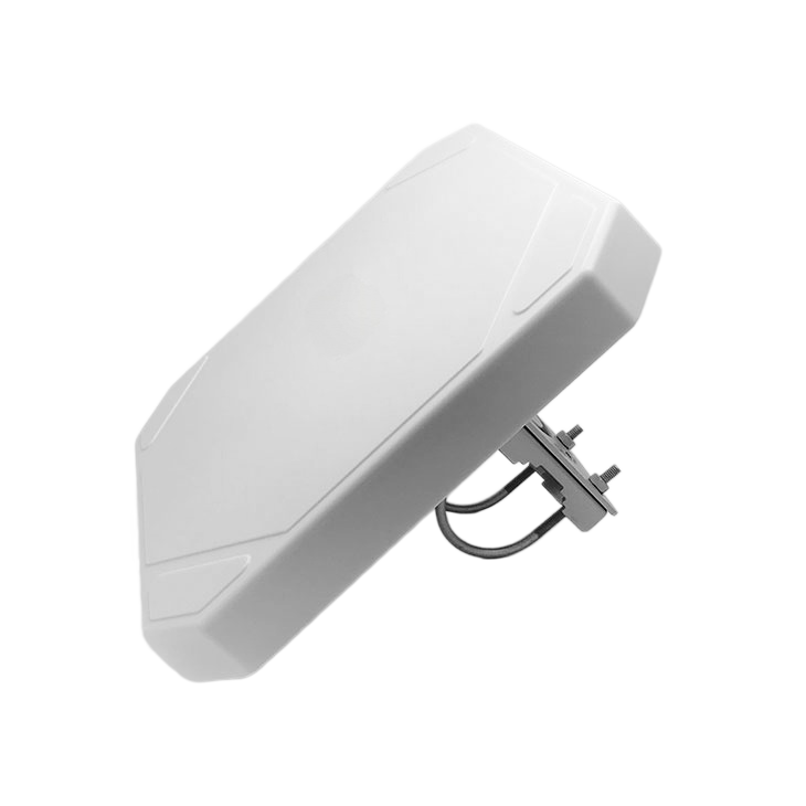
9dBi UHF RFID Panel Antenna
9dBi RHCP panel antenna, 60 by 55 degree 3dB beam-width, N-Type Female at 50 ohms, IP67 sealed, 255 by 255 by 30 mm.
View Details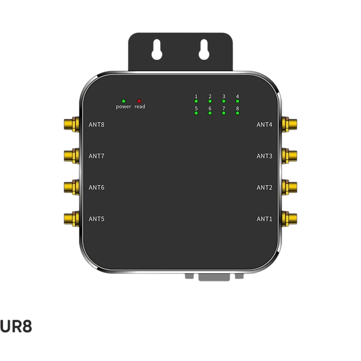
UR8 Eight Port Fixed UHF RFID Reader
The UR8 fixed UHF RFID reader drives eight 50 ohm SMA ports, reads 550+ tags/sec with circular polarization, and links to a host over RJ45 or RS-232.
View Details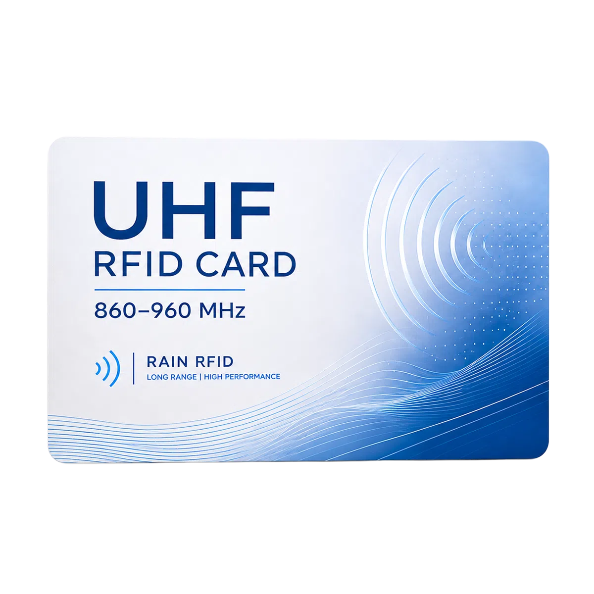
UHF Card | 860–960 MHz RAIN RFID Card
Standard CR80 UHF RFID cards with Impinj, NXP UCODE, Alien Higgs chip options. Ideal for parking, asset tracking & warehouse inventory. OEM/ODM available.
View Details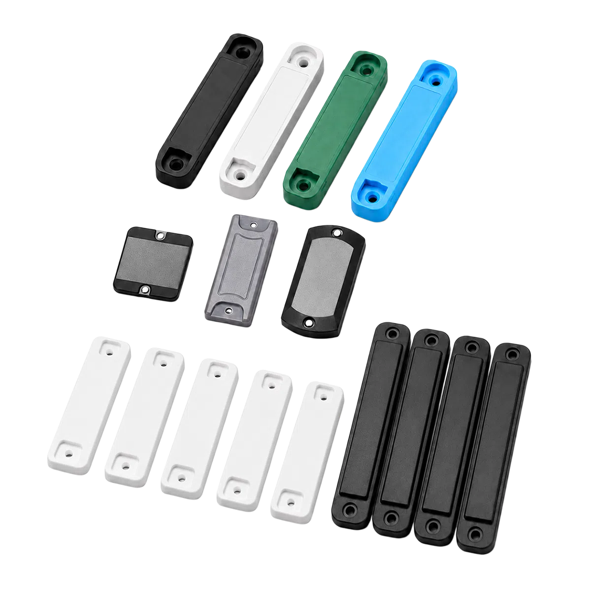
ABS UHF Anti-Metal RFID Tags for Industrial Asset Tracking
Durable on-metal RFID tags from CedaGlo for asset management, warehouse racks, tools, data centers, utilities and equipment tracking.
View DetailsAim It on Your Own Site First
5dBi with RHCP, an 80° by 70° pattern at 3dB, and a front-to-back ratio of ≥17dB. One part number covers 902-928MHz and 865-868MHz, so a rollout across both bands stays a single line item. Send us your pole diameter, the tag you read, and the reader you are pairing it with.