12dBi Panel Antenna for Fixed UHF RFID Read Points
12 dBi of gain, a 40° by 38° 3dB beam-width, and a VSWR of ≤1.3.
The 12dBi Panel Antenna concentrates the UHF field into a 40° by 38° 3dB beam-width, which is what a fixed read point needs when tags cross a known line. Two configurations cover the two frequency ranges, 902-928MHz and 865-868MHz, on one enclosure and one bracket. The port is N-Type Female at 50Ω, with a maximum input power of 20W and DC Grounded lightning protection. It clamps to poles of φ30-φ50(mm) and weighs 2.66kg with the mounting bracket in place.
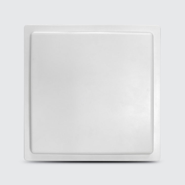
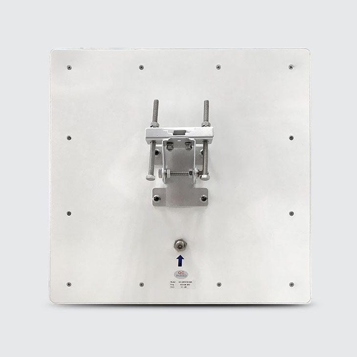
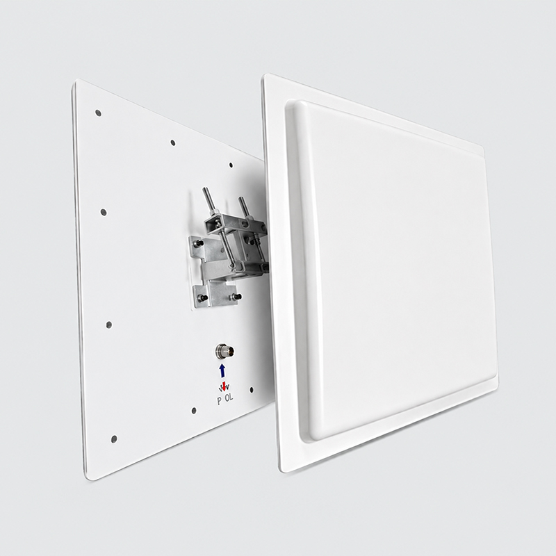
- 902-928 / 865-868 MHzFrequency range options
- 12 dBiGain
- RHCPPolarization type
- 40° / 38°3dB beam-width, H and E
- VSWR ≤1.3Standing wave ratio
- ≥17dBFront to back ratio
- 50ΩInput impedance
- 20WMax input power
- DC GroundedLightning protection
- N-Type FemaleConnector type
- 445*445*30 (mm)Dimensions H*W*D
- 2.66kgWith mounting bracket
Overview
The 12dBi Panel Antenna is a directional UHF panel for fixed read points: 12 dBi of gain inside a 40° by 38° 3dB beam-width, RHCP polarization, and a VSWR of ≤1.3 at a 50Ω N-Type Female port. It is the shape you reach for when tagged goods cross a known line and the field needs to stay on that line.
The figure worth a second look is the front to back ratio of ≥17dB. At a gate or a dock door, back-to-back read points are the normal layout, and a panel that rejects what happens behind it is what keeps one lane from claiming the other lane’s tags. Maximum input power is 20W at that same port.
Mechanically there is one build behind both configurations: an off-white ABS radome over an aluminum radiant board, 445*445*30(mm) and 2.66kg with the mounting bracket, clamped to poles of φ30-φ50(mm), with DC Grounded lightning protection at the port. Explore the full range of UHF RFID antennas.
Key Features
RF Performance
- 902-928MHz or 865-868MHz
- 12 dBi gain
- RHCP polarization
- 3dB beam-width 40° H, 38° E
- VSWR ≤1.3, ≥17dB front to back
Rated for the Outdoors
- IP67 sealing
- -40°C/+60°C operating range
- Rated wind velocity 60 m/s
- DC Grounded lightning protection
- Off-white ABS radome
Mounting and Interface
- N-Type Female connector
- 50Ω input impedance, 20W max
- 445*445*30(mm) panel
- 2.66kg with mounting bracket
- Pole mounted, φ30-φ50(mm)
Features & Functions at a Glance
Choose Your Configuration
| Feature | 902-928MHz | 865-868MHz |
|---|---|---|
| Best for | Lanes, gates and dock doors on a 902-928MHz reader fleet | The same work where the fleet runs on 865-868MHz |
| Form factor | Flat panel, pole mounted, one enclosure for both | |
| Shared RF and hardware | Identical in both configurations | |
| Gain | 12 dBi | |
| Polarization Type | RHCP | |
| 3dB Beam-Width | 40° H-Plan / 38° E-Plan | |
| VSWR | ≤1.3 | |
| Front to back Ratio | ≥17dB | |
| Input Impedance | 50Ω | |
| Max Input Power | 20W | |
| Connector Type | N-Type Female | |
| Dimensions H*W*D (mm) | 445*445*30(mm) | |
| Weight | 2.66kg (with mounting bracket) | |
| The only difference | The row below is the one value that changes | |
| Frequency Range | 902-928MHz | 865-868MHz |
| Site and mounting | Common to both configurations | |
| Sealing | IP67 | |
| Operating Temperature | -40°C/+60°C | |
| Installation mode | Pole mounted | |
| Support Pole Diameter | φ30-φ50(mm) | |
| Rated Wind Velocity | 60 m/s | |
| Lightning Protection | DC Grounded | |
Mounting — the mounting bracket ships with both configurations and is included in the 2.66kg weight. It clamps poles of φ30-φ50(mm). No other mounting hardware is listed on the configuration sheet, so none is quoted here.
Both configurations share one enclosure and one bracket; the frequency range is set in the factory and picked at order time. Every value in this table matches the full Specifications section below.
A Closer Look at the Hardware
One-Piece ABS Face, Nothing to SnagThe radiating face is a single piece of off-white ABS with no screws, no vents and no label breaking the surface. There is nothing for grit or standing water to sit in, so the whole maintenance routine is a rag.
A Standard N-Type Port, Facing DownThe N-Type Female connector sits on the back plate and points downward once the panel is upright, so water runs away from the coupling nut rather than into it. Any standard N-Type Male jumper fits, so the cable is never a special order.
It Arrives Ready to Clamp a PoleLift the radome away and the bracket is already on the back plate: a hinged plate and two U-bolts that close around poles of φ30-φ50(mm). The 2.66kg quoted on this page is that whole assembly, so there is no separate kit to price or wait for.
Specifications
Electrical
- Frequency Range
- 902-928MHz / 865-868MHz
- Polarization Type
- RHCP
- Gain
- 12 dBi
- 3dB Beam-Width. H-Plan
- 40°
- 3dB Beam-Width. E-Plan
- 38°
- VSWR
- ≤1.3
- Front to back Ratio
- ≥17dB
- Input Impedance
- 50Ω
- Max Input Power
- 20W
- Lightning Protection
- DC Grounded
Mechanical
- Connector Type
- N-Type Female
- Dimensions H*W*D (mm)
- 445*445*30(mm)
- Weight
- 2.66kg (with mounting bracket)
- Radome Material
- ABS
- Radome color
- Off-white
- Radiant board material
- aluminum
- Operating Temperature
- -40°C/+60°C
- Sealing
- IP67
- Installation mode
- Pole mounted
- Support Pole Diameter
- φ30-φ50(mm)
- Rated Wind Velocity
- 60 m/s
Every row above is transcribed from the 12dBi Panel Antenna configuration sheet. Items not listed there are not offered on this page.
Why Buy the 12dBi Panel Antenna From CedaGlo
Numbers You Can Measure
Nothing here is a claim you have to take on trust. Every line we publish is measurable on a bench with a network analyzer, so you can hold what you read against what we wrote before a single unit ships to a site.
The Band Is Yours to Pick
Tell us which frequency range your readers work in and we build to it. Enclosure, bracket and port stay the same either way, so a site drawing you approve for the first region still holds when the second one comes online.
Try It on Your Own Lane
Ask for a sample before you commit to volume. Mount it where the traffic actually runs, read your own tags on your own equipment, and decide from what you saw rather than from what a supplier wrote about it.
Built to Stay Orderable
A single build covers everything we sell under this model, which keeps spares simple years into a rollout. Supply windows, warranty length and replacement handling are confirmed in writing with each purchase order, never assumed from a web page.
Frequently Asked Questions
How much gain does the 12dBi Panel Antenna deliver, and over what beam?
The configuration sheet lists 12 dBi of gain, a 3dB beam-width of 40 degrees in the H-Plan and 38 degrees in the E-Plan, and RHCP polarization. Those are the antenna figures we sell against. Read range at a portal also depends on the reader, the tag and the site, so we quote what the antenna does and let you measure the rest on your own lane.
Which of the two configurations should I order?
Match the antenna to the band your readers already run. One configuration covers 902-928MHz and the other covers 865-868MHz. Everything else is the same part: same radome, same bracket, same N-Type Female port. If your fleet is mixed, send us the split and we will quote both against one site drawing.
What is the antenna built from?
An off-white ABS radome over an aluminum radiant board, with an N-Type Female connector on the rear plate. The mounting bracket ships with it and is included in the quoted weight of 2.66kg. Every material name here is taken from the configuration sheet rather than from a product photo.
How long will it stay orderable, and what does the warranty cover?
One build covers both frequency ranges, so spares stay simple across a long deployment. Supply windows, warranty length and replacement handling are commercial terms rather than data sheet lines, so we confirm them in writing on your order instead of publishing a number our company has not committed to.
How does it hold up outdoors?
The sheet rates the unit IP67 for sealing, gives an operating temperature of minus 40 to plus 60 degrees Celsius, a rated wind velocity of 60 m/s, and DC Grounded lightning protection. These are the design figures from the configuration sheet; we are collecting the underlying test reports and will pass the numbers on when they are in hand.
What does installation need from us?
A pole of φ30-φ50(mm), a coaxial jumper with an N-Type Male end, and a grounding path at the mounting point. The bracket handles the rest. For repeat orders, lead times and returns handling, ask for the terms in writing with your quote.
Related Products
5dBi UHF RFID Panel Antenna
Passive UHF RFID panel antenna: 5dBi gain, RHCP, 80 by 70 degree beam at 3dB, IP67 sealing, 0.73kg with bracket. Covers 902-928MHz and 865-868MHz.
View Details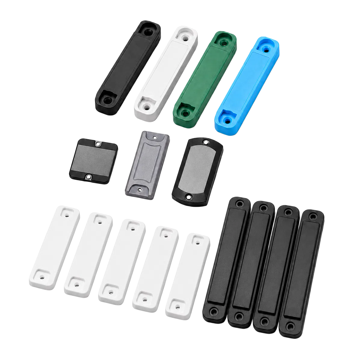
ABS UHF Anti-Metal RFID Tags for Industrial Asset Tracking
Durable on-metal RFID tags from CedaGlo for asset management, warehouse racks, tools, data centers, utilities and equipment tracking.
View Details
Printed RFID Labels | Custom Finished RFID
Custom finished RFID labels from CedaGlo with printable face stock, adhesive backing, barcode, QR code, serial number and UHF/NFC chip.
View Details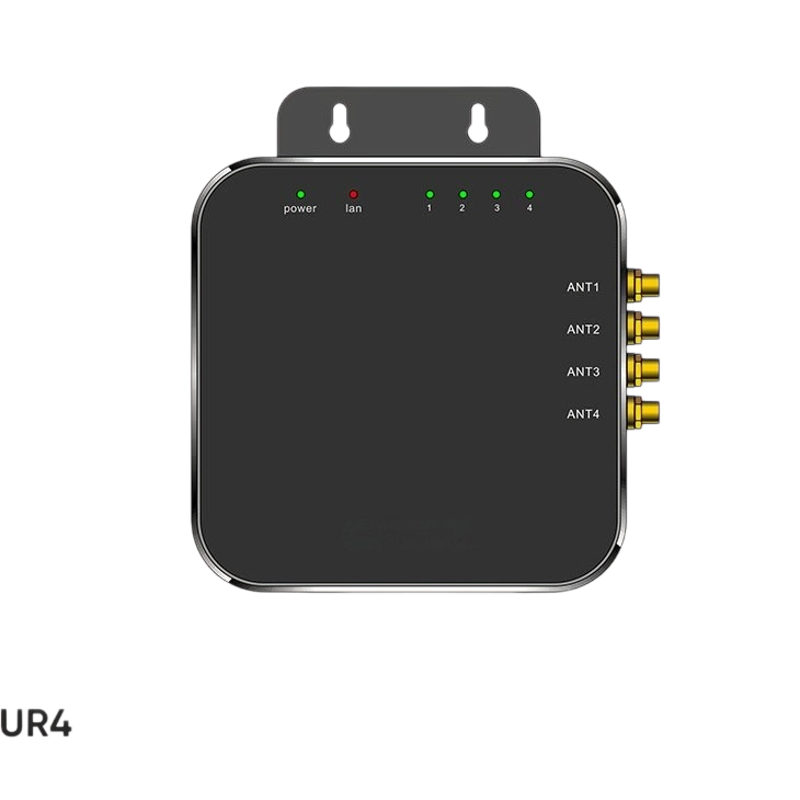
UR4 Fixed RFID Reader
Four-port fixed UHF RFID reader. 4 channel 50 ohm SMA port, 1300+ tags/sec fastest read rate, engine based on Impinj E Series chips. RS-232 and RJ45.
View DetailsTwo Frequency Ranges, One Hardware Build
12 dBi of gain inside a 40° by 38° 3dB beam-width, with ≥17dB front to back, so the panel covers one gate and not the one next to it. Only the band changes at the factory, which keeps stock, brackets and drawings on a single line item across regions. Send us the reader band and the tag type.